|
|
|||||
After
that somewhat off-topic portion, we're getting back to business! Routing is very boring, I almost kinda dread doing it. It's certainly not as exciting as thwarting guards on my way into the shop! You have to punch in the individual depths of parts for each item in the unit, then sit there watching it rout in case it messes up. If it does, it's usually operator error, such as entering the wrong value in the computer.
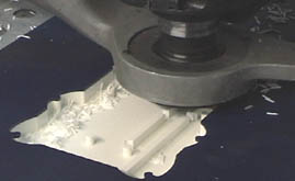
Here is a close-up of the router routing the front half of the SNESp case. The bit (in that circular metal vacuum thing) goes back and forth, cleaning out sections at a time. Typically, I use a 1/4" and 1/8" bit to cut out the case. The 1/4" bit does the main clean out work (as shown above), then, to drill the screw-holes and button openings, I use the 1/8" bit. I also sometimes use a V-shaped bit to chamfer the edges of items. With the SNESp, I chamfered (or beveled if you will) the edges of all the brushed aluminum plates. When everything inside is cut, I then tell the router to cut the exterior shape full depth, which separates the item from the block of material. After that, burrs and paper-thin bits of material are removed with an X-Acto knife and a sanding block. With the case pieces cut, the next step is to color them. I use vinyl material to color them because it's faster than paint, more forgiving and I'm used to working with it. With the SNESp, I choose a metallic light & dark blue scheme. Those colors will accent the brushed aluminum plates. Also, I choose brass screws because brass/orange goes with blue.
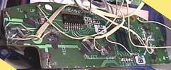
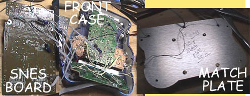
The wiring of the SNESp was pretty run-of-the-mill. Unlike the Atari 2600, you can get composite video right off the board with no additional circuitry. I did replace the SNES's 7805 power regulator with a low drop-out version for increased power savings, however. One thing I had to work around was the controller. The above photo shows the circuit board of a SNES controller. It's been hacked down a bit, however. Anyway, the SNES has a latched input controller. (Most/all systems after the Sega Genesis do, actually). Instead of having a wire and circuit for every button (as with the Atari 2600) the latched input controller combines all the button data into a couple address lines. That's how a system like the N64 can have all those buttons on the controller but with only 3 wires on the plug. So, instead of re-working the system, I decided to just put the original SNES controller circuit board inside the unit. (hey, there was enough room). This is also how I did the PSp's controller. I then wired my new control switches directly to the appropriate spots on the SNES controller.
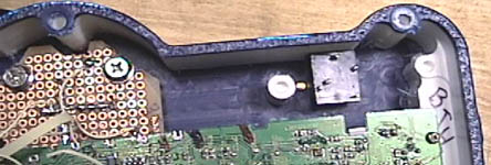
Here is part of the SNESp's interior. You can see a screw post (the white thing near the middle), the TV's circuit board, and the trigger controls. For the buttons & controls I use tactile pushbutton switches. These switches are cheap (around 20-30 cents each) and mount easily to standard PCB's. I highly recommend them to anyone building a portable unit. As for the controls themselves, I switched gears and used the original SNES control pad & buttons. I just liked them, I guess. They went well with my color scheme! The Select/Start button was custom, however. When building a portable unit, a large problem is always power consumption. Your average pocket TV uses 500ma of power. Add that to the SNES's power intake (around 250ma) and you've got 750ma. Also, just adding wires between things increases the power drain. SO! As with the VCSp Gold and the PSp, I replaced the cold-cathode light tube on the TV with 2 white LED's, again from Radio Shack online. (here is a link to that item). Basically what I do is remove the tube, and stick an LED on each end, thus 'simulating' a tube. I also have to remove the power supply for the tube. Typically, there's a spot on the TV's board which sends +5 volts into the cold cathode tube power supply. This power supply then steps up the voltage to something like 800-1000 volts to power the tube. After I remove the power supply, I power the white LED's off that 5 volt pin (it's convenient). I typically put about 20 ohms resistance in front of the LED's and then wire them in parallel. This drops the TV's power consumption from 500ma to around 250ma.
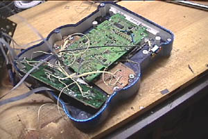
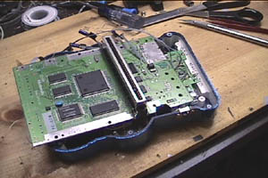
Here is the front half of the SNESp with most of the guts inside. To save interior space, part of the screen sticks out the front of the unit. There is a raised portion on the front of the unit to accommodate this. This is the same trick I've used on the VCSp Rev 5 and the PSp. (old tricks are the best tricks)
Here is the SNES board being put (almost) in place. The cartridge will stick straight out the back. I spent a lot of time deciding if the cartridge should stick out the back or slide in. I decided to have it stick out because it keeps the overall size of the unit smaller, plus it doesn't interfere with game play. This illustrates a common issue with construction of this stuff. You have to balance the trade-offs. Sometimes doing something as simple as having the cartridge insert sideways will add another inch or two to the unit's overall size.
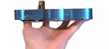
Here is the SNESp from the side, with the back plate not attached. As you can see, all the components of the unit are flush in the 1 inch thick front half. However, the unit needs a battery, so I created a back plate out of brushed aluminum to fit between the front half and the rear "T" shape that holds the battery and the L & R shoulder buttons.
The construction
continues!
|
|||||