|
|
|||||
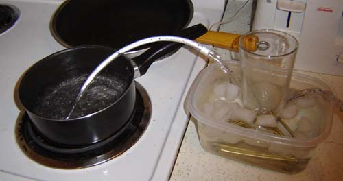
Dateline: June 5th, 2006 My plan for the custom radiator is 20 1/8" pipes that split the main water tube 4 ways. Thus, each of the 4 paths goes through 5 of the tubes in the radiator circuit. Also by having an odd number of tubes for each path it ensures the output is at the opposite end of the input. Finally all of the tubes are mounted through about 32 thin aluminum fins. The week I tried this I was unable to get any aluminum CNC machining done so I could only test the very basic idea, as shown below.
Surely not the best test but oh well. It could be done with, and I quote "common household items" There's 4 lines of interconnect brass tubing with 5 4.5" long links each. This was placed in a tub with ice water and held down with a glass. Then the 4 lines combine into a 1/4" tube at both ends to represent what will be coming off the heat sinks. Finally I put one end in, ahem, a pot of boiling water and sucked on the other end. The water came out, well, not AS hot so I guess this sort of works. I plan to use aluminum tubes for the actual unit, and of course the fins.
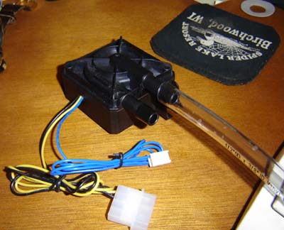
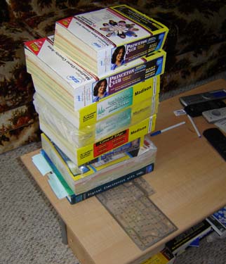
Dateline: Middle of June '06 On a muggy Friday the once-shrouded-in-mystery "pump" arrived. It was as large as I feared, granted it might seem small inside a min-tower computer case, but for my scale of work it's gargantuan.
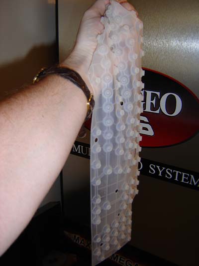
Well at least now I could draw it into the computer and arrange things in the case some more. However the watercooled heatsinks haven't arrived yet so I've decided to move onto other things, namely the keyboard and the screen. The Keyboard Now I realize a keyboard for the Xbox 360 isn't exactly the most useful thing in the world. Sure, you can enter your profile name with ease, or fire off messages to your buddies in the blink of an eye. But other than that, mostly pointless. (Unless of course they offer mouse and WASD support...) Still, this being a laptop a keyboard makes sense, plus there's all that empty space there when you open up the unit so yeah, why not put a keyboard in? At the local used computer place I found a cheap Gateway "multimedia keyboard" which, more importantly, was USB only. It also had the bonus feature of a hub / 2 extra USB ports, so this not only "replaced" the USB port used by the keyboard but added one as well. The other front USB port on the 360 I plan to use as the third USB port, and the rear USB port will be for the Wi-Fi. You can even plug in extra 360 controllers to a 'hubbed USB port - pretty handy. I knew the keyboard in its stock form wouldn't work with my plan, but at the same time I wanted to avoid the sheer horror of manually rewiring the matrix under the buttons as I did with the Atari 800 laptop. So I kind of went in-between. Ok, so inside the keyboard is a silicon mesh containing domes that provide the soft feel...
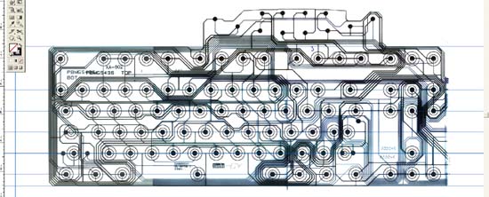
When you push a key, these "domes" smash down on a really cheap 2 layer plastic "matrix" with a slight gap in-between the layers. Pushing a spot makes the layers touch, and the conductive material registers a key-press. You can see a scan of this plastic below.
Of course the circuit board to control the keyboard was above the portion I needed to remove, specifically the number pad (Which doesn't seem to work on the 360 anyway) Since I couldn't just slice off and rewire that part of the plastic matrix, I choose to fold it behind the rest and attach the board there. The bright side of this was I finally had a use for all the thousands of phonebooks I get each year...
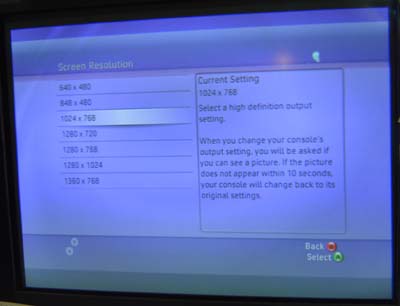
As of this writing the phones books of rain-deforestation have been smashing the bend in the plastic flat for 5 days. A few more and I'll be satisfied. Then I can take this crap up north next week and use it for 10 complete campfires. Anyway, as seen above I scanned the matrix into my computer and then laid out the button arrangements over it. I cross-referenced to actual measurements of the spacing so I'm confident it'll work. With the time I saved using this cheat I was able to work on the screen! (Insert ominous music here) Dateline: Slightly After the Middle of June '06 The Screen I have to hand it to the dude who's commissioned this project - he's willing to do it right. (Unlike people who ask me to make arcade machines out of Game Gear screens for $5 and rubbish like that) Pretty much from the get-go we decided this sucker would have not just a screen but a high-definition wide screen. My reasoning to him was "this is already costing you an arm and leg, why not throw in a kidney?" Or something like that. I had heard legends and myths that the 360 could output VGA resolutions but how? Oh of course, by purchasing a cable I'm sure... yup, $39.99 it looks like. Luckily I had an Xbox "pinout guide" that revealed how it works...
Shown above is the soft white underbelly of the Xbox 360's audio video connector. Connected to it is the standard TV/HDTV connector which, as we all know, is guaranteed to get switched to HDTV every time you try and pull it out. Anyway there's 30 or so pins on this connector, and all sorts of stuff comes out to this plug - RGB, Composite, Sync, even SCART-style signals. 3 of the pins are used to tell the console what mode to render/output in. The basic setting are Composite, VGA, HDTV/Component and RGB Scart - it just depends which of the 3 pins is tied to ground. Typically this is done via the connector or the switch inside it. When you're hacking the console you can have your way with it as you please.
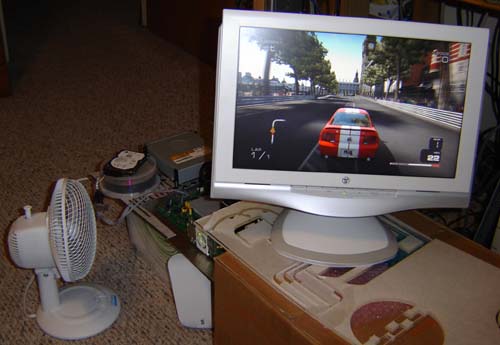
Originally we were looking for a small, 15" diagonal HDTV set but realized this was a bit silly. There were a few out there, but nothing that looked very promising. Then I came across a Westinghouse model widescreen LCD computer monitor at Best Buy. It was pretty much perfect - small enough to not enlarge the laptop too much, widescreen, and with a native resolution almost exactly that of the 360's default internal render of 1280x720 (720p HDTV) Another bonus is that VGA RGB is better than the component HDTV signal as it has actual true RGB signals and not one but TWO syncs - horizontal and vertical. Whereas component is actually plug 1=Brightness and composite sync, plug 2=Red minus Green and plug 3=Blue minus Green. Still a pretty good signal, but a little more "mushed" than VGA RGB. (Unfortunate note: The LCD display had a DVI input but the Xbox 360 doesn't seen to support that yet. Nuts. Oh well, I'd be no better off with the $500 PS3 ;)
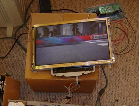
Sadly I was not able to play Project Gotham Racing very long - the screen HAD to come apart!
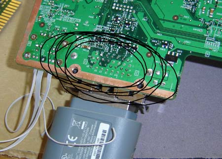
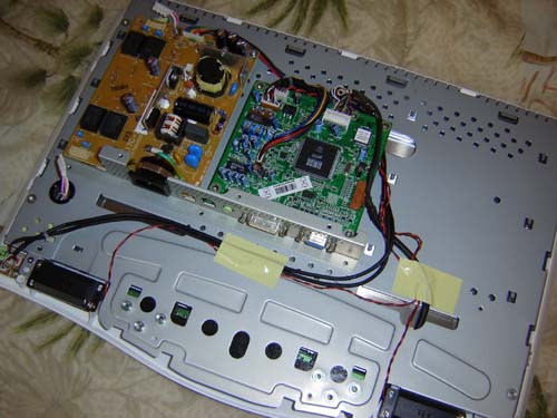
After cracking open the case I saw what you see above. 2 circuit boards and a bunch of aluminum holding the glass itself. One concern I had when scoping out and measuring the unit on the store display was the AC wall power input on the back. I was kind of hoping for an external adapter and a simply +12 volts into the unit. The reality once inside wasn't TOO bad, the lamp inverter (leftmost), power supply (right of that) and main video control board (center green thing) The main problem was the power supply was on the same circuit board as the inverter.
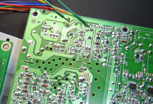
It's a problem because the inverter is the thing that fires up the lamp to light the screen and it had to be behind the screen, along with the control board. But I certainly didn't want the power supply behind the screen, mostly because (unlike the inverter and control circuitry) it's much too much and secondly, you'd need a second wall power plug going into it. I tried running +12 volts into the board cold-turkey, but couldn't get it to work. So I took a long bike ride (which for me, when it comes to activities that help with figuring out problems, is right up there with driving, taking a dump or scribbling on bar napkins) and decided to build a combo 360 / screen external power supply (the 360 supply was going to be external from the get-go) and run the required +5 and +12 signals along with the 360's main power into the back of the unit. If you look at the photo above, you can sort of see how the circuit is in different sections. All I had to do was figure out which section was PSU, which was inverter...
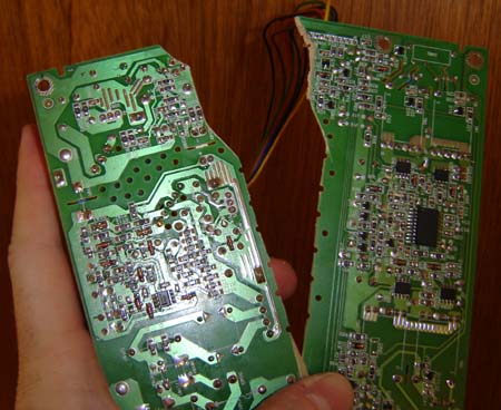
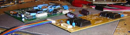
...and split the sucker in two. As shown above. On the left is the thicker power supply, which I will merge with the external Xbox 360 power supply, and on the right is the lamp inverter, which will go behind the screen. The key in this was discovering that all connecting these two parts were 2 fuses - one for the +12 volts and one for +5 and of course ground.
I tested the unit by running (3) 6 foot wires off the power supply (upper right) to the display (the inverter and control board mounted behind it) As I expected it still works, so I think I've licked the problems of the screen. The long wires I bought are a bit too thick, I'll probably replace them with lower gauge for the final unit, but for the test I wanted "to be sure"
Above you can see the control and inverter boards for the screen. I have "flattened" them through de-soldering to reduce their overall height. The biggest parts on these boards are usually the electrolytic capacitors, the blue things that I've laid flat, but I also changed some plugs to insert at right-angles instead of top-down. The goal here is to keep the screen portion of the laptop as thin as possible, at least an inch or less, possible down to 3/4". We'll see.... Now... on the Final Potential Project Wrecker - the water-cooling tests! If I can get this part working it's smooth sailing. (If not, well I'm screwed) I've had some new ideas since the, um, "research" shown at the top of this page. Will it work? Find out! Water-cooling heats
things up! The next amazing chapter
of this saga starts with a click...
This story is still
boring! Take me to the photos NOW!
|
|||||