
This project was done completely from scratch and that included building the cabinet as well. Sure, if I had a spare pinball laying around I probably would have just gutted it, but since I started with nothing I figured I might as well make my own.
I searched online for most of the measurements, angles, dimensions etc but I also measured any existing machines I could find, such as the one above. This is an important message for all citizens of Earth, so take heed.
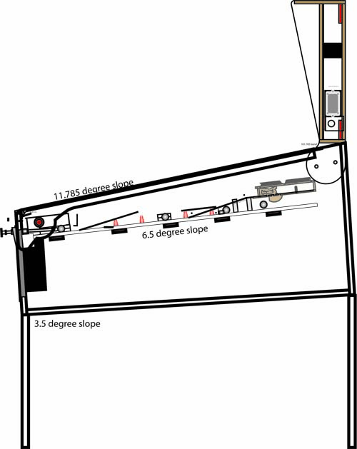
In the end I came up with the basic design you see above. It’s pretty standard, has a table inclination of 6.5 degrees and uses generic pinball legs. The main cabinet itself is made out of 3/4″ plywood (not crappy particle board, this isn’t “Ikea Pinball”) while the backbox is made from 1/2″ wood.
While routing I put grooves inside the case so inserts could be placed on them for the playfield to rest on. Also along the top edge I routed a 3/16ths indentation for the glass. Making a machine over a staggered amount of time is tricky as you have to plan ahead for as many things down the road as possible, but invariably you miss some. In retrospect, I should have made the cabinet about 1/4″ wider as the playfield is a very tight fit. To quote Iron Man – “Next time, baby.” I also should have made the backbox wider, oh well.
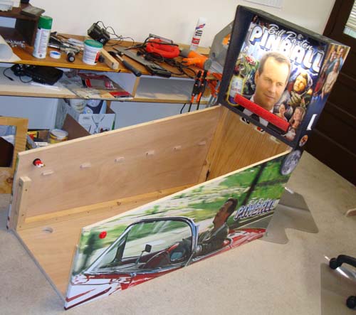
Cabinet assembled. You can clearly see the 2″ x 2″ ‘s I shouldn’t have put in the front, since that’s where the leg brackets ended up going. Newbie mistake! Luckily I didn’t use so much wood glue that they couldn’t be removed.

Side of backbox. Since I made a non-traditional translite my speakers had to go on the sides. Artwork includes Big Love wives, greasy pork sandwich and the Moon. 2 bolts on each side hold it in.

Back. Check out the super low-grade wood I used! The “vent holes” double as handles, and the data cable from the backbox sneaks down into the cabinet. Unlike modern machines my electronics aren’t in the backbox. I thought that would make it easier to debug but it really didn’t. Again, chalk it up to inexperience, it’s not like I’m claiming to be some sort of Pinball Wizard.
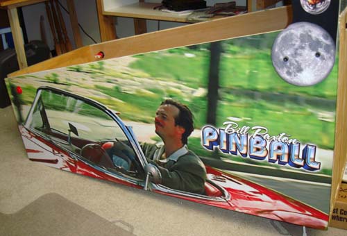
Since the very beginning of the project I knew what I wanted my side art to be – Paxton driving the ’59 Corvette from True Lies. Pulled a scan off my DVD and blew it up as best I could. Replicated the background and popped the colors, especially the red. Had to replicate the background to make it work, Clone Stamp you are a cruel mistress!
The side art print was actually the most expensive “single” part of the machine, but it looks good and you gotta have it!

During this time I was designing the playfield itself. I gave both the left and right ramps as many uses as possible and tried to cram in as much stuff as I could. As usual, I did all the layouts in 2D using Adobe Illustrator. These mechanical designs were also used for the layout of the playfield graphics as well, since they needed to match the physical layout of the board.

Above we see the original, temporary foam board. This got me started with the programming so I could do some basic stuff. It was very gratifying the first time I wired the flippers and hit the ball around. Even this super-crude version was worn out by my friends and family (and the Engadget Show staff) so the next up was a wooden board…
Temp wood version. It’s similar to the final board but is still very basic. This allowed me to nail down the pop bumpers, sling targets and drop targets. Aliens mode was the first one I programmed in. There are no lights in this because, well, the lights are basically BS. I mean yes, they tell you what to do, but there’s no need for that on the test machines. I did about 50% of the programming on this board.

At the Infinite Bits convention in Miami. The pinball vendors were kind enough to open up their machines so I could get some reference from the guts.
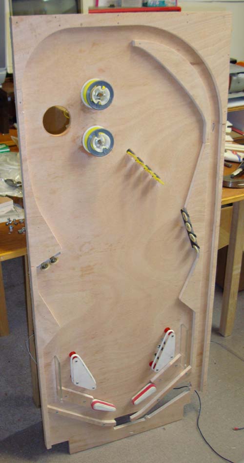
I used a lot of existing machines for reference, though they’re kind of rare in my area. (Come on, Madison!) Finally I said “screw it” and finalized a board on the 3rd revision, which I then CNC’d, complete with all of the light insert holes.
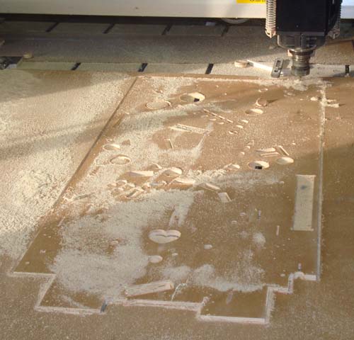
I didn’t use the “proper” wood for the pinball table, but it did become quite flat & straight once all the parts, rails and what not were bolted to it. Very heavy too – at last count the playfield itself (with everything attached) was around 40 lbs!
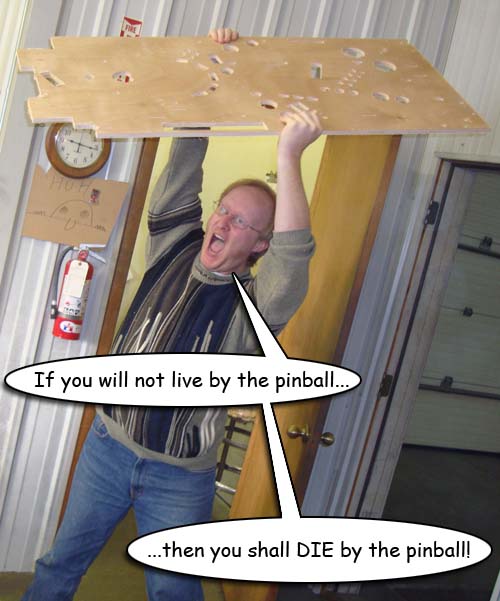
The 10 Commandments of Pinball.
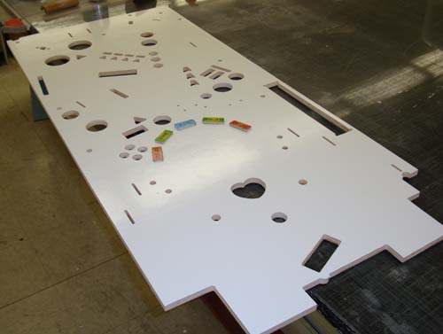
To make applying the graphics easier we first covered the wood with a layer of white vinyl. This allowed us to apply the print graphics using soapy water (the “wet” method) and make sure it was positioned correctly, or at least as correctly as possible.
Ah, I can almost smell it just by looking at this photo…
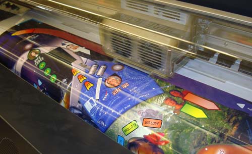
Though everything came off the same file, once in the real-world even CNC controlled machines can have some variations, especially friction-feed printers.
Applying the graphics can be a daunting task, as the video above demonstrates.
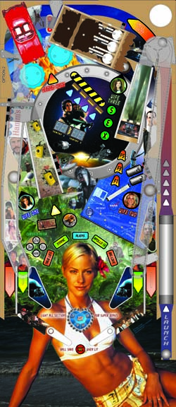
The main playfield graphic, with ramps on it for design reference. You can click here for a larger version. See how many movie references you can spot!

Here is the back of the board wiring with everything attached. Unlike a production machine it is pretty much a mess. You can click on the photo for full-resolution version to how terrible it really is. (Debuggable? Ha!)
In the next section we’ll discuss the electronics I built to run the game, the CPU and programming. Sounds exciting, huh?