
Sometimes my creations have elaborate origins, like “I’ve been working on the idea for 15 years” or it came to me one day in the bathroom. (Bathrooms and cars being places where I have most of my best “idea bursts”) But I’m sorry to say the NES Micro had no such “stroke of inspiration” behind it. Rather I just had an extra NOAC (NES-on-a-chip) Asian joystick game laying around and figured I may as well do something cool with it instead of letting it collect dust.
You may recall that last year (2004) I also cobbled together a NOAC portable, so the thing here was to do something special. As many of you know I keep close track of Nintendo’s monthly Gameboy hardware releases so of course I knew of the GBA Micro. Then it struck me – why not make an NES micro? Ridiculously small screens and cramped controls shouldn’t ONLY be reserved for newer games! My path was set!
STEP 1 – Hacking up the NOAC board and converting the connector
Most of those cheap overseas NOAC game joystick things (or Super Fun Mecha Joy-Joy Stick Fun units as I call them) have 60 pin Famicom (Japanese) cartridge connectors on them. So as with my last NOAC portable I had to hand-wire an adapter. The American NES has a 72-pin card edge connector.
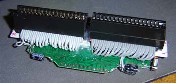
This is a working NES clone, complete with American 72-pin cartridge slot.
To keep it small as possible I wired the adapter by hand, rather than using a converter as with, say, a Game Axe, and kept the wires short. I used 2 old floppy drive cables for the cartridge slot. Don’t call me cheap (well I am, but) I just couldn’t find the correct 72-pin connector for the cartridge off Digi-Key. They’re sort of obsolete these days. You may notice a gap in the center – this is fine as the center pins on a NES cartridge are intended for the expansion slot on the bottom of the American NES. Therefore they go unused. (No such extra cartridge pins were present on the Famicom)
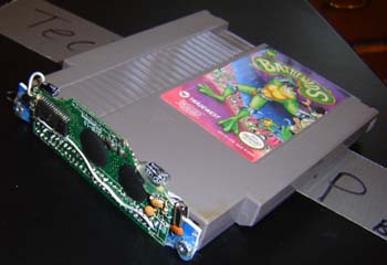
The NOAC, wired and plugged into a cartridge from an era when Rare didn’t take 5 years to make each game.
STEP 2 – Designing a really small case
Designing the case is always the hardest part for me, or at least the most time consuming which I guess could be construed as the same regardless. On top of the usual headaches and dial caliper marathons was the fact I intended the NES micro to be as small as possible and fit the following guidelines:
|
Not much wider than a NES cartridge |
|
|
Only a little taller than an AA battery |
|
|
Not much thicker than a AA battery on top of a NES cartridge (.55″ + .75″) |
|
|
As close to the X Y width/height as a GBA Micro as possible. A GBA Micro is 4″ x 2″ on the X Y. I didn’t worry about matching the Z/depth as the NES cartridge is thick and makes that impossible. |
Lofty, sure, but I figured I could handle it. In case you’re just joining us here on www.benheck.com here’s the steps I take in designing one of these things:
|
Boot up Adobe Illustrator, get a Pepsi to drink |
|
|
Measure all the parts the portable requires. Typically cartridge, system guts, screen size and batteries. Re-draw parts as vector objects on computer. |
|
|
Arrange parts in a basic square that’s the intended size of the unit. See if it fits, if not increase square size. In this case I started at 5″ x 2.5″ but ended up using 5.25″ x 2.65″ |
|
|
Do side-angle drawings to check the depth of the unit. Illustrator isn’t 3D so I have to do this in various 2D drawings. (Autocad would be nice to have but eating Ramen noodles for a year to afford it wouldn’t be) |
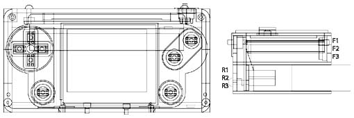
This unit has a bit of a first as there’s hinged battery doors. This was a space issue, it was really the only thing I had room for. Even the buttons were hollow so the tact switches could be INSIDE them rather than under, saving space inside the unit for batteries:
Hollow buttons – an old trick from my Vagabond 2000 days
STEP 3 – Cutting the case and assembling it
As with many of my more recent portables the parts for this were cut out of Acrylic and engraving plastic using a laser engraver. This allows for much smaller and more accurate parts than can typically be had with a bit-based CNC router.
After the parts are cut they are stacked and glued together. See, most of the unit was made from 1/4″ plastic, so the pieces get stacked to form the actual case. By having different layers I can put various level screw holes, spaces, etc inside the case.
Decals are also printed (using a thermal vinyl printer) and attached to the surfaces. This is a very important part of the process as it’s important for the thing to look good!
STEP 4 – Stuffing everything inside the case and hoping it all fits (I mean… why wouldn’t it? 😉
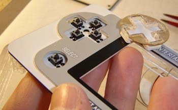
And now comes the second hardest part of the whole process – installing all the guts. See no matter how much planning I do in the design phase there’s always tons of monkeying around to get everything to fit. I started with the controls, which basically consists of tact switches under the buttons. The wiring is simple so instead of having PCB’s made (which would exceed the LCD screen in expense!) I just do it by hand.
In the below photo you can also see the 2.5″ LCD screen has been installed. Most of this stuff is secured with hot glue – yes I COULD screw everything in place but if some slight discrepancy came along (which they always do) then I’d be screwed! Hot glue at least allows… “variance” (That’s a fancy word to use so nobody notices me slathering the stuff everywhere)
I ended up using a 2.5″ screen, a little bigger than a GBA Micro. And yes it looks sharp, like the GBA Micro. But that’s only because it’s smaller! Rule of graphics – anything look better smaller.
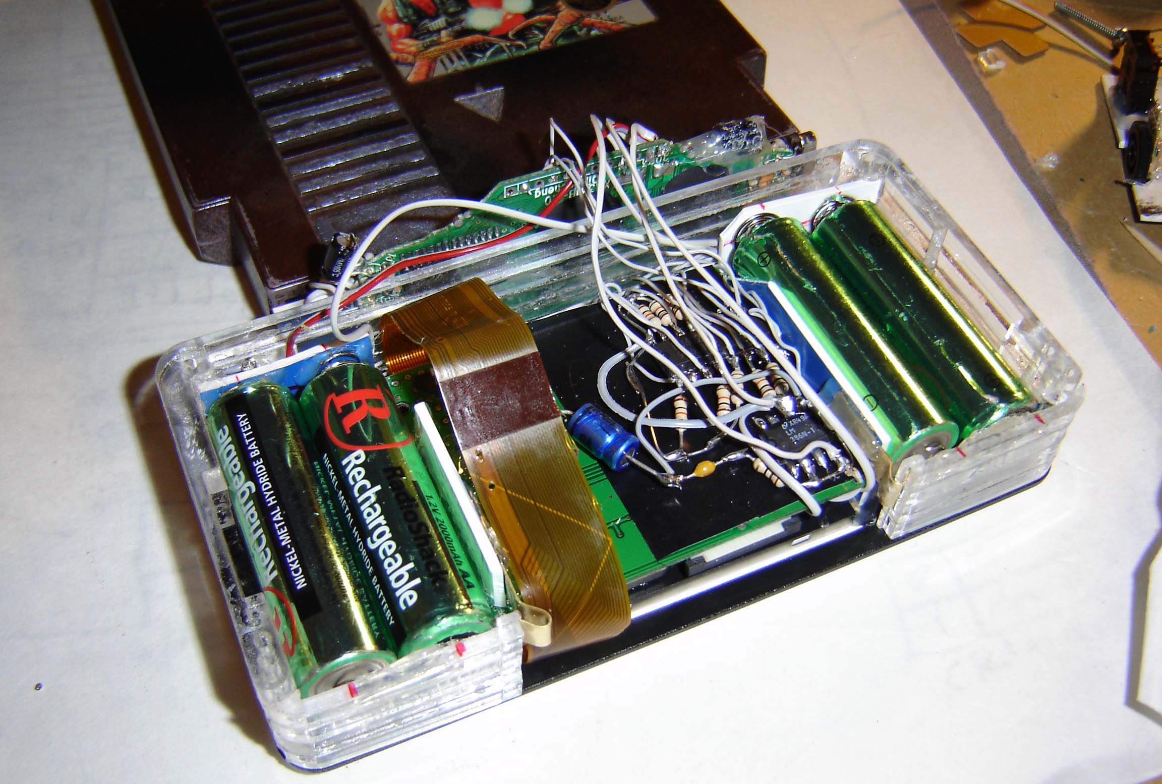
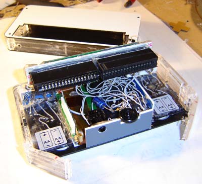
The front half of the case. With screen and controls/control wiring installed. Note the battery doors swung out at the bottom.
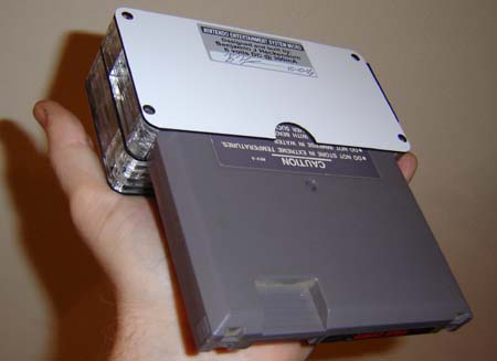
This next photo shows how the batteries fit inside the case. The main design “idea” was the case would be not much thicker than the screen or batteries, and not much wider than them set side-by-side. This photo is a good example of that. When building something like this the biggest “things” are always 1) system guts 2) screen 3) battery and 4) game cartridge. Everything else, like power supplies and IC’s for audio amplification are all considered secondary (at least in my book) That “extra stuff” can be fit anywhere!
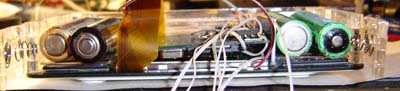
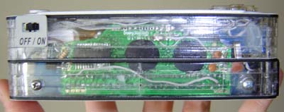
Side/end view showing the vertical layout of the parts. Batteries, screen and front portion.
For the battery contacts I used the metal terminals from a pocket TV case (Shocking I have several zillion of those laying around) The big springs on the negative sides were cut down a bit to relieve the pressure on the battery doors. Here you can see the NOAC has been attached. Really all that hooks to it is +6 volts, ground, Audio, Video and 3 wires for the controls.
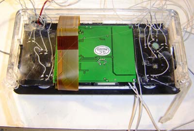
The completed guts of the front side of the case, sans volume knob and headphone jack. CLICK TO ENLARGE
Here’s a close-up detail of the hand-wired parts I put just behind the screen. (This is the “extra stuff” mentioned a bit ago) A NES controller is a bit more complex than say an Atari 2600 joystick so the shift register IC and some pull-up resistors are required. You can also make out the 386 audio amp, its capacitors and the volume knob. Oh and the headphone jack. Note the overly long LCD-to-controller board ribbon cable coming off the screen – that thing was a pain!
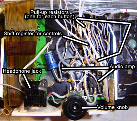
Detail of the control/audio circuitry inside the NES Micro
The NOAC guts are then stuffed into the top of the unit as shown below. It sort of holds the battery tabs in place (blue thing on middle left of photo) It’s packed so tight nothing is gonna go anywhere, believe me!
The unit with the NOAC board installed, speaker wired and rear half of case ready for final assembly.
Finally the rear half of the case is set over the front and screwed in place. I put some nuts on the NOAC board, this allows screws to go through the top of the rear half of the case and attach itself to the NOAC board, as seen below. Since the cartridge will push and pull at that point this is pretty much required for extra strength. Oh and you can also see the power switch.
I thought about coloring the case sides but thought it’d be cooler to leave it transparent so a person can see inside. You know, to appreciate it or something
End view showing the NOAC board and what not
Here’s some assorted views of my NES Micro to look at:
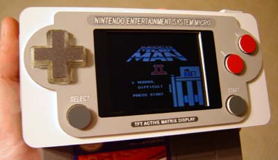
Front view with game running. When the batteries get weak (like 5 volts total) the screen gets a little dimmer but still fine. Because of this normal alkalines, rather than rechargeables, are best.
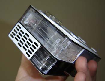
The speaker ended up on the lower left hand side. Space was so tight this was the only place it’d fit. Oh well. Chalk one up for weirdness.
View from the rear. Look – screw wells! The first time I’ve ever used them, shocking I know!
And now finally, my NES Micro compared to a GBA Micro….
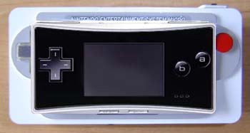
NES Micro compared to GBA Micro (Micro simulated as there’s no way I’d buy one of those things)
OK so it’s not AS SMALL but considering it takes full size NES cartridges and was built basically by hand I’d say I didn’t do a bad job in shrink-a-fication.
Well that’s about all I have to say about my NES Micro. Don’t worry, when Nintendo releases their next “Gameboy Of The Year” in 2006 I’ll be sure to make some sort of comparison project then as well 😉
2 thoughts on “NES Micro”