
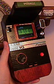
 The Finished Product. The Atari 2600 VCSp.
It all started one day while I was at work . . . I’m a graphic artist and I use computers everyday, and of course they sometimes (quite often) don’t work right so I end up on the phone with tech support. So there I was, listening to Musak, sitting in my chair, waiting, waiting… My mind drifted away… to Atari.
Ah, Atari. I’m sure most people in their 20’s or 30’s have SOME memory of that fine system, that wondrous achievement, that pillar of an acme of an apex that defined an industry! The point may seem moot now, but, you must realize, had it not been for Atari, the videogame industry probably would not be the same as it is today (read: HUGE)
There had been videogame systems before the Atari 2600, but the 2600 was the system that appealed to the most people and had the best selection of games. Kinda like how computers and the internet didn’t take off big-time until Windows 95 came out. (and you anti-Microsoft people KNOW it’s true) However, Atari wasn’t a HUGE hit right off the bat. In fact, some say that it would have died a quick death had it not been for a technical anomaly in the system…
GEEKY TECHNO-BABBLE!
The Atari 2600 could only display a background, 2 players and a ball at the same time. So, think of the 2 tanks in Combat, those are the 2 players. And the gunshot is the ball. If you wanted more players, you could take 1 player and flicker it back and forth quickly, to make it look like 2. (It’s called multiplexing, and they did that A LOT on the Nintendo).
But that looks crappy. And some Atari 2600 developers refused to use it. Luckily for the 2600, it had a thing called H-Strobe. I can’t recall if it was a glitch or something actually designed into the 2600, but, at any rate, it allowed a player to be duplicated up to 3 times, in a horizontal fashion.


Without H-Strobe, and then WITH H-Strobe.
I bet a lot of you are thinking “So what?” Well, the thing is, when you have 2 players being multiplied 3 times each, you can have up to 6 players across. And each player can be as tall as the screen, so you can multiply them that way as well. Are you STILL thinking “So what?” Well, recognize this????
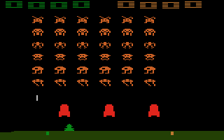
Ah ha! Got ya! Whose laughing now, huh? WHOSE LAUGHING NOW? Well, this game could not have been made had it not been for the H-Strobe effect. See the SIX rows of aliens! Ha! Math wins the day! Space Invaders was such a huge hit when it came out for the Atari in 1980 that people bought systems just to play the game. And with that, Atari rocketed into the stratosphere! (until 1983-ish when they had wasted so much money they were doomed)
I believe Jimmy Carter said it best – “A chicken in every pot, an Atari hooked up to every TV.” And maybe he didn’t that say… but he should have!
Ok, so I got off-subject. Well, not really. I have to show my passion for Atari, don’t I? Well, anyway!
I sat there on the phone waiting, and I started doodling. Doodling, is, you know, what people did before they had Photoshop. So, I was like, hm, hm, portable Atari 2600… that’d be neat… cartridge here, batteries here, circuits here, screen, controls… On paper it looked very much like a Gameboy Color! I continued doodling. I thought, “Hm, maybe it’s possible… I’ve heard that the Atari 2600 was a very simple machine… Perhaps I could rip the chips off it and make a custom circuit board to fit in a small box… hm… Hm…. HMMM…..”
Tech support came back on and I was snapped back into work. But the idea was in my head!
I am ashamed to say this, but, it must be said. At the time (February 2000), I did not own an Atari 2600. Probably because I have a 7800, and it will play all the same games, but still, is that any excuse? And those 7800 controllers, UGH! Which monkey designed those, and when will he be sent back to the zoo? Besides, I knew for a fact that the 7800 had a lot more chips and things that I would have to figure out, so I didn’t want to tackle that. Also, the 7800’s are somewhat hard to find, so I didn’t want to rip mine apart. Also, I wanted the portable Atari to be pure. A pure, 100%, older-than-dirt vintage Atari 2600 unit, with wood grain and everything!
A friend of mine had one that he (gasp!) was not using. We pulled it out of storage and I began my task!
Well, I unscrewed the thing, pulled it apart, and looked inside. A circuit board, with 4 switches mounted on top, a cartridge hole, a big capacitor, and the rest was covered with metal armor plating. All in all, the circuit board was about 10 inches wide by 6 inches tall. Small, yes, but too big for a portable unit.
I used my manly Herculean force to rip the metal shielding off the circuit board. Underneath, I found the 3 Sacred Chips, and a whole mess of resistors and capacitors.
“Crap!” I thought, “This is way to complex to re-design a circuit board for!”
Ok, sure, it could be done. But, I’m not really a circuit board making expert.
So, I went to sleep that night in despair. The circuit board sat there, mocking me.
“Ha ha, Ben! You can’t figure me out! I’m too big! Too big! Why, look! Look at all this wasted space on me! Put there only to frustrate you!”
And then it hit me. Wasted space! I grabbed the board.
“Hey! Let me go, you fiend!” it cried from the depths of its silicon soul.
“Hush, you!” I rasped at it “I have hit upon an idea that’s rather clever!”
And I looked over the board. Sure enough, entire sections of it seemed rather
USELESS! I traced the circuit-lines… hm, some could be by-passed. If they can do it
on hearts, they can do it on Ataris!
I decided it was time to visit the band-saw…
Research over the Internet had led me to believe that a Composite Video output could be obtained from the Atari 2600’s circuits. For anyone that doesn’t know, composite video is like the VIDEO OUT port on your VCR or DVD player. (SUB-NOTE: Actually, the Atari 2600 is capable of doing LUMA/CHROMA output, which is similar, if not the same, as an S-VHS hook-up)
Anyway, I was interested in composite video out for 2 reasons. One, it would give a better picture. Two, if I could get a video signal from the chip itself, then I could do away with the RF modulator! An RF modulator is the thing inside the Atari that makes a TV signal. It takes the video signal from the chips and makes it into a Channel 2 or 3 signal that any old piece of crap TV can pick up. It’s the way everyone hooked up their Atari, because it was the ONLY way. Besides, I highly doubt that the crap-ola Zenith TV’s circa 1981 had composite video inputs. But they might have, heck they had laserdiscs back then!
But, who needs an RF modulator in the Year 2000? I sure don’t! I removed the portion of the circuit board that used the RF modulator. It cut 2 inches of length off the total. Yeah! Now it was the size of a portable unit. (almost – more to come)
A power wire of some sort had to be jumped because of this amputation. Also, the RESET and SELECT switches had to re-wired, since they (originally) were on the section that was hacked off. However, they were simple! Each switch, RESET and SELECT, used a pin off the RIOT chip, and went to ground. YAWN!
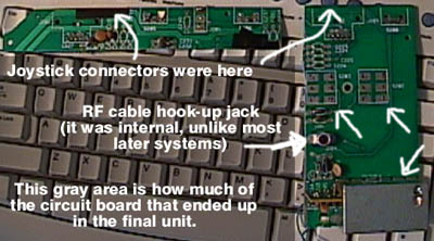
Here are the portions that were sawed off the original board. The silver square things on the right hand side were where the RESET and SELECT switches were. The silver thing in the lower-right hand corner is the RF modulator.
I now had a circuit board that was quite smaller. But… I was having trouble getting video to work…
I found some article off the Internet (where else?) that explained how to get composite video off your Atari. They called it a ‘bare-bones’ approach. Well, I tended to agree, because it only partially worked!
Before I explain how I got it working CORRECTLY, a little history. There are 3 chips inside the Atari 2600.
* The 6507 Processor. This blazing chip could reach speeds of 1.19 MHZ. (I’m not sure what it could do over clocked, maybe run Half Life, who knows?). The 6507 chip is quite similar to the 6502. The 6502, as you might recall, was used in everything from the Nintendo 8-bit, to the Apple II, to the Atari 400/800 line, to the Atomic Bomb, and even, in an altered form, to the Turbo Graphix-16. Yes, that chip got around, alright.
* The RIOT Chip. This chip did stuff like look at joystick ports, switches, I/O crap, and stuff of that nature. If you refer back to the last page, I mentioned wiring the SELECT and RESET button directly to it. Now you know why! Also, the RIOT contained the Atari 2600’s RAM. A whole 128 BYTES!
(In perspective. Let’s say you have a computer with 64 megs RAM. That’s 524,288 times more RAM than the Atari had.)
* The Stella Chip. This is the chip that did all the graphics of the Atari 2600. It was called Stella, also the code-name of the system. “Stella” was the name of an Atari employee’s bicycle. Hey, it was the 70’s, alright?
Ok! So, according to this web site I found, if a person hooked a lead to pins 2, 5, 7 & 8 of the Stella chip, they got LUMA output. And, by hooking a lead up to a certain resistor, they got CHROMA. And by hooking the LUMA and CHROMA together, you get COMPOSITE. And with COMPOSITE, you could hook that to a VIDEO IN on a VCR or TV and get a nice, clean signal! My intention was to use a portable TV unit as the screen for the Atari, and the portable TV’s usually have VIDEO IN, so, that’s what I wanted to use.
I hooked up the video as described in the article I found. It worked, but the colors weren’t quite right. They looked OK in simple games, such as 2600 Pac-Man (but who wants to play that?), but more complex (ahem BETTER) games like Pitfall had incorrect colors and REALLY complex games like Pitfall II just looked like utter CRAP. Hm…
I scoured the Internet some more, and found another method of getting video off the Atari. This method involved a complex circuit, involving resistors and things. But it still hooked up to the same pins on the Stella chip.
“Hm!” I thought “There must be a common ground here someplace. But where?”
I decided to use BOTH methods. I put a potentiometer on each wire. Anyone that has
made it this far into my boring tirade probably knows what one is, but, if you don’t,
I’ll tell you. A potentiometer is basically a volume control. A variable resistor. Using the
potentiometers, I was able to adjust how much signal came off each wire.
Well, it worked. I adjusted each and got a correct signal. The vines, dirt, trees and bricks
of Pitfall all looked right. I drilled small holes in the circuit board of the Atari and
attached the potentiometers right to it! If I ever needed to adjust the signal, I could.
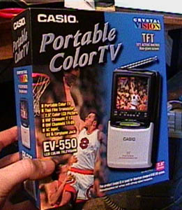
The TV I used. It’s a Casio EV-550. The screen is a 2.5 inch TFT (thin filament transistor) active matrix, which means moving images don’t ‘smear’ like they did on old laptops or the original Gameboy. The EV-550 can tune in TV stations, but I didn’t think that was a feature my Atari needed. All I needed was the video input so I could get the signals from the Atari. As for the case, I tossed that as well and only kept the screen, speaker and the circuit board. It was a far, far better thing it did than it had ever done.
Sound was easy. It involved hooking one lead up to the junction of a resistor and a capacitor, then attaching the other lead to ground.
The case for the unit was actually the hardest part to design. The first month of the project was wiring and figuring out what did what on the Atari board. Up until now I had mostly just torn things off and re-wired them. But the case was the thing I actually had to design. The case had to contain a circuit board (the original Atari guts), the video screen and its circuit board, the cartridge slot, the batteries, the controls and the power/volume switches. Most importantly, it had to look COOL! In order to look ‘cool’, it had to be as small as possible. Obviously this depended on the size of the main circuit board…
The rear half of the unit.
The unit was done in 2 halves. The rear half contains nothing but the circuit board and the cartridge slot connector. There might be some electric tape back there, too. Early on I realized that the cartridge would have to stick straight up. It saved room, since it sat on TOP of the circuit board, and not beside it, on the same level (like a Gameboy).
Had I made the cartridge slot like the Gameboy, it would have made the length of the unit about 4 inches longer at the top! Besides, sticking straight up is 1): a sun-screen 2): more like the original Atari. 3): different!
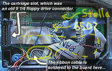
As you can see by the above picture, the circuit board and case was about as small as it was going to get! The blue thing in the lower left corner is one of the potimeters that I used to adjust the video. (see a few pages back). It took about one zillion years to solder the ribbon cable between the circuit board and the new cartridge slot, but it allowed me to put the cartridge slot wherever I wanted.
Now for the Front Half of the case!
The front half of the unit. (interior) 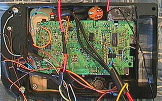
The front half of the unit had a lot more stuff in it, of course. That’s where the action
is, you know!
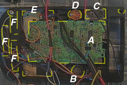
LEGEND (of Zelda)
A): The circuit board of the portable television. The portion near the ‘A’ has the screen, so it’s the thickest. To the left is just circuit board, since that’s where the batteries were on the original pocket TV. This space allowed me to place the Control Pad Circuit Board (E) right on top on it. (well, it appears BELOW it here). In the lower left corner of the TV circuit board you can just make out a screw that attaches to control circuit board, holding the TV circuit in place.
B): The speaker. It’s actually the speaker that came with the pocket TV, so, yeah! It’s heavily hot-glued into place, and several holes were (manually!) drilled in the case to let sound through. Just to the right of the speaker is the back of the Power Switch. Luckily for me, the original Atari power switch could turn 2 different circuits on and off at once. I wired it so it would turn on the TV and the Atari at the same time, but on different circuits! They must have been thinking ahead back in ’77…
C): The place where the 9 volt hooks up. It had to be tough to with stain the insertion force!
D): The volume control knob. It’s an off-the shelf model from Radio Shack. The silver colored knob also came from Radio Shack. It looked the most vintage 1970’s of all the knobs they had.
F): This thick section of the case holds the batteries. I crudely drew where they are. If you look back a few pages, you can see them from the front.
Getting the slots and compartments for the batteries was a bit tricky, since the Computerized Router that I used to make the case could only do XYZ up and down, not from the left or right. The cutting bit could go up and down (for depth) and left right up down or diagonal (for shapes.)
It’s hard to explain kinda. The best analogy would be that it was like designing a level for Doom, where it seems 3-D, but you’re really only making a 2-D map.
Or maybe… Ever see one of those pin-things, where a zillion pins are under glass, and you can put your hand against it to make a shape? Well, it’s like that. Everything has a position and depth, but that’s it. Course, I reckon most molds and castings are kinda like that.
Well, that’s about it for the story behind the making of the Atari 2600 VCSp. Thanks for coming along for the ride!
11 thoughts on “Original Atari 2600 VCSp”