
Bill Paxton Pinball (BPP) started long ago, in the distant yesteryear of 2005. At the time I was collecting parts to build my Neo Geo custom arcade cabinet and I had these thoughts:
- Hey, it would be cool to have a pinball machine!
- I should build my own, it would be a interesting challenge.
- What would the theme be?
- Ah! Bill Paxton Pinball. Swish, done.
That took about one total minute of thinking. I then began my quest…

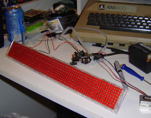
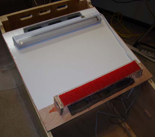
Aside from some random doodlings for a backbox design, I started by by lasering a 64 x 8 frame in which to mount (by hand) 512 standard-sized red LED’s. This may seem insane, and yeah, I guess it was, but I really wanted this thing to be as custom and hard-core as possible. Plus LED matrix segments are actually kind of expensive.
I had actually started experimenting with LED matrix displays even back when I did the Neo Geo cabinet in 2005. Check out the story here and notice the “coin counter” I added.

One of the very first test circuits for Bill Paxton Pinball, circa 2005. I couldn’t even find 7 matching LED’s back then!
My very first idea was to use a Basic Stamp to run the display itself. Keep in mind the Propeller was fairly new at this time and I was really only familiar with the ‘Stamp. The original design called for a series of multiplexers to address the display column / row and an external RAM / EEPROM to hold the display / animation. The idea was the ‘Stamp would only refresh it when need be, otherwise a binary counter would just “rake” the data from the IC’s to the display.
Always keep your Atari 800 handy, no matter what project you’re working on.
This idea sort of worked but not really as well as I wanted. Plus by this time even though I was using the much-faster Propeller it still wasn’t fast enough for a flicker-free display, at least without machine language (which I wasn’t using at that time) SPIN is fast but not enough to refresh a 64 column display fast enough to be both bright and flicker-free.
Above is a simple test where a value is multiplied on every column and sent to the display. As you can see it’s a lot dimmer than the final product since it’s being erased and redrawn over and over.
What I ended up doing was putting an 8 bit shift register on every column of the display so the display itself was the memory. Data is shifted in, 1 or 0, 512 times per cycle and the display remains in that state until rewritten.
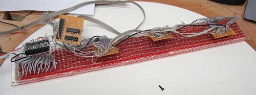
Replacing the multiplexers with shift registers (and nearly doubling the cost of the display)
This allows full control of the display with only 3 wires: data, clock and latch. Also you can create a scrolling effect by latching it every 8 clocks. Additional bit-shifting code allows the display to be scrolled up and down.

Looking back now it would have been easier to use resistors as the “wire bridge” in the above photo but hey – as long as I’ve still got teeth I’ve got great wire strippers.
By time this I was using the Parallax Propeller, as previously mentioned. The first code I wrote for BPP was the display driver. Although the Propeller has a built-in character set I had to make my own to fit the ratio of the display. (Looking back now I wish I had done a 64 x 16 matrix, oh well) The character set goes from 0 (zero) to Z and is ASCII-aligned. Therefore a SPACE is “;” since SPACE in ASCI is 32, I didn’t want to add 8 useless characters between that and “zero” (40). RAM wasn’t tight at first but it was near the end!
The display driver can do the following:
- Display score (static, scroll in from top, scroll in from bottom)
- Single-frame message (static or scroll in a specified speed)
- Scrolling message (can be as long as you wish with variable scroll speed)
- Direct memory-to-display output (used with animation driver)
Commands for the display are sent from the main game kernel in forms such as this:
fr.scroll(string(“HIGH;SCORE;CLEARED”),1_000_000)
whereas 1_000_000 is the number of clocks per column of scroll
fr.static(string(“INSERT;COIN”),0)
whereas 0 indicates not to scroll this onto screen, just stick it there.
ScoreLoop(16)
whereas 16 indicates to start the score at +16 pixels (off the bottom of the screen) at which point it will scroll up to center. ScoreLoop(8) would just display the score in the middle, no scrolling.
(You can download the entire source code for reference, see Part 3 of this story)
Next up was animation. The first trick was to analyze the file structure of a 64 x 8 1 bit (black & white) Windows bitmap, using a binary viewer.
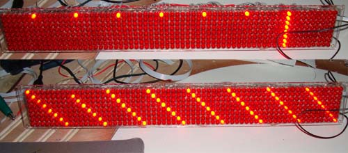
A bitmap starts with the bottom left pixel, goes to the right, then up a line and over again. This in no way translates to how my display memory is arranged, as the example photo above shows. I did a test pattern in the bitmap file so I could identify how the pixels were laid out in the bytes.
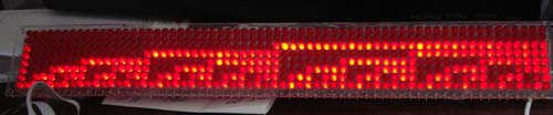
I wrote some code to flip the bits and make the bitmap appear on the screen off an SD card, as seen in the video above. It worked but was kind of slow, well, the bit operations at least. The ultimate solution was to write a separate program that reads a sequence of bitmaps off the SD card, rearranges the bits, then stores them in the spare 32k of the Propeller’s EEPROM in the same sequence as my display uses. These can then be loaded quickly into the frame buffer and displayed at will during the game.
Next up was mounting everything in the backbox (sometimes called “head”) of the unit. I had designed & printed the translite back in spring of 2008, so I had that ready. For illumination I used a cheapy fluorescent bulb package from Menard’s. Not shown here, but I actually ended up painting over the lamp to make the display a bit dimmer so it wouldn’t reflect as much on the glass. Oh well, rookie mistake.
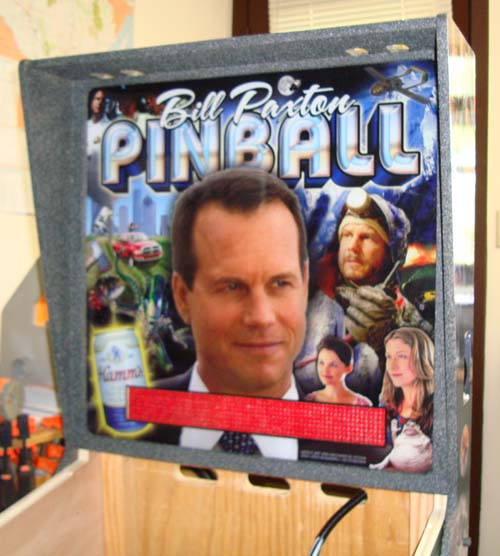
The backbox with all artwork and display. You can see the cable coming into the cabinet in the back. It contains: AC power for lamp, audio, data for display and display power (+3.3 volts)

Spot the differences! It’s just like one of those lame MegaTouch games!
The translite was actually done with 2 separate translucent prints placed atop each other. This creates richer colors and deeper blacks. It’s a similar method to movie posters that are printed in reverse on the back to ensure high quality. Also, one of the prints had certain areas “knocked out” so those spots would appear a bit brighter on the board.
In the next section we’ll discuss building the cabinet and iterations of the playfield itself…
5 thoughts on “Bill Paxton Pinball “Making Of” part 1”