
Let’s say it’s Friday night and you’re hankerin’ for a good old fashioned fast-paced game of Ladybug. Or perhaps Venture. So you whip out the Colecovision and suddenly realize – it uses those ancient RF modulator switches! Curses! That’s not even remotely modern. Now a composite video input, that’s clearly the bleeding edge of video quality. (Or at least better than the old switchbox) In this article I’ll detail how to get such a signal from your Colecovision, along with audio signals. Let’s get started, that evil Zaxxon robot needs to get kicked in the junk!
Stuff You’ll Need
(1) 1k resistor
(1) 1k variable potentiometer (Radio Shack # 271-280)
(1) NPN transistor. Usually called a 2N4401-ND. (Radio Shack # 276-2058 )
Electrical tape
Solder & an iron
Some A/V cables. I used Playstation cables (video, L & R audio) and cut off the end.
Beer and potato chips (Optional, but recommended)
Step 1
Rip apart your Colecovision (or take it apart carefully using the screws) It can be a little tricky pulling the top of the case from the bottom, they’re well-joined around the expansion port area. Some prying may be required.
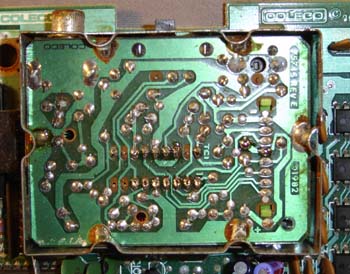
Remove the screws holding the RF shielding in place. At the top of the board (away from the cartridge slot) you simply can’t miss the huge metal box – this is the RF modulator section. Pry the lid off the top and you should see the following:
Step 2
This circuit is so simple I’m not even going to bother drawing a schematic. It’s a basic amplifier for the video signal. (Also seen in my book re: the NES) Take a look, there’s an 18 pin IC on the RF board – this is what converts the Coleco’s color difference video into composite and RF signals a TV can use.
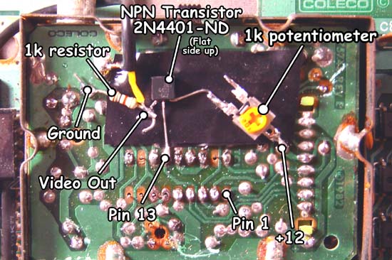
1) Solder the single pole (the wiper) of the potentiometer to the indicated spot on the board. This is +12 volts, and as you can see, also connects to the 4th down connector between this board and the Coleco (the spots between the yellow posts)
2) Solder either leg of the potentiometer to the rightmost leg of the transistor, with the transistor FLAT SIDE UP. This gets the “boost” voltage for the video. By turning the pot you can adjust the amount of video amplification. Most large TV’s, you turn the pot all the way up as shown (very little resistance) but I’ve seen some LCD screens that need it dialed down a bit. By using a pot you’re covered should you need adjustments for your specific display.
3) Solder the center leg of the transistor to Pin 13 of the IC, as shown. This is the video input from the IC.
4) Solder the left and final leg of the transistor to the 1k resistor. Then solder the other end of the resistor to GROUND. Like most PCB’s, ground on this board is anything that touches the outer edges.
5) Now it’s time to connect your video cable. Solder the center wire of the cable (usually the colored one, visible after you strip it) to the left leg of the transistor (same one that goes to the resistor) Solder the ground / shield / outer wire of the cable to ground.
Wham, now you have composite video!
Step 3
Time for some sound! This is even easier. Seriously, that penguin on the homepage could do it. (Or me after about 12 beers, which would be about the same) Down to business! While there’s sound signals near the IC, the best place to grab them is off the sound generator IC of the Coleco itself. It’s located just below the RF box, just to the left of the heatsink and just above the BIOS. (Wow, that’s like Google Earth level detail, eh?) Here’s the IC…
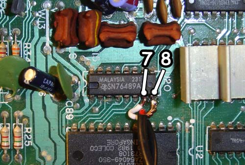
1) Though the Coleco is mono, you can nevertheless hook the sound up to both left and right audio cables to create an encompassing “wall of sound”. Using your audio cables, connect both inner wires (red and white) to Pin 7 of the sound IC as shown. Finally, hook both grounds / shields / outer wires of the cables to Pin 8. You could use any ground on the board, but Pin 8 is handy. Actually, as long as the video cable’s ground is plugged in you don’t even need to connect the audio grounds, but you might as well since your soldering iron is heated up anyways.
There you have it! Composite video and audio from your Colecovision. Hopefully this works for everyone!