
For Bill Paxton Pinball I designed all of my own electronic circuits. Again, I wanted it to be a very low-level project, rather than say a PC running the pinball through a parallel port or something like that.
Throughout this section, click on the text links to see the parts used along the way (opens in Mouser.com in a new window / tab).
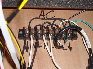
AC power terminal block. A heavy gauge cord goes through a main power toggle switch then to this block. Live, neutral & earth are replicated a couple times for the 3 AC items in the unit: PC power supply, 24 volt power supply and backbox fluorescent bulb.
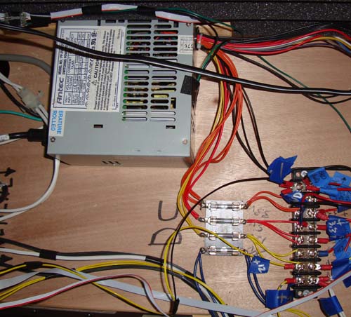
PC power supply (very very useful things) is jumpered to always on (see ATX pinout for more info) and supplies 3.3 volts (driver boards) 5 volts (solenoid control) and 12 volts (audio amp and Propeller development board supply). The Propeller CPU itself is 3.3 volts but it has a separate regulator for itself on the dev board.
The power mains goes through a bank of fuses, only 2 of which I blew during the entire project, strangely enough. This then goes to a secondary terminal block which supplies DC power to the various components and, as you can tell, is as overloaded as a 1970’s Christmas tree in a house with 1 outlet plug.
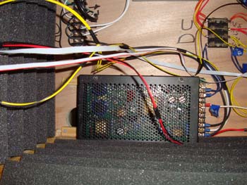
24 volt supply. This is a generic CNC power supply I found off eBay. Solenoids and flippers run off a variety of voltages depending on manufacturer, but for the purposes of this machine 24 volts was sufficient. The flippers are a bit weak so I had to really work hard adjusting the ramps to ensure the ball would make it up then. In the final machine you can’t really tell, so that’s the point I guess.
With the power supplies out of the way, let’s move on to the circuitry itself…

Here is an overview of the main circuitry in the pinball:
- CPU development board
- Sound & Music SD card slots
- Input / Output control for board for 64 bits of light and 32 bits of input (playfield inputs)
- Solenoid control board. 16 bits of 24 volt solenoid control, 16 bits of motor control, 32 bits of input (mostly cabinet buttons / tilt sensors)
- Motor control board.
- Audio amplifier.
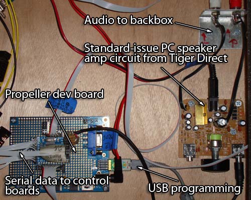
The main game logic consists of a Parallax Propeller development board with a USB connection to a PC for programming. The Propeller has 28 I/O lines for general use as well as a 64k EEPROM. The bottom half of the EEPROM is used for program memory, whereas the top 32k is free and is used to store display animations and high scores. Once you’ve programmed the pinball with a PC it retains the data and can run on its own.
At the start of this project I figured I’d use a cheap, small PC to run this, but along the way I went away from that because: a) that would be what anyone else would do b) I wanted really low-level TTL logic everywhere!
So often in this modern world people are far removed from how their electronics or even computers work. I wanted to get back to that, and this project certainly fit that bill!
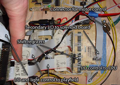
Here is the main I/O board. It accepts serial commands from the CPU which are fed into the output shift registers to control the lights, and also sends back serial data from the input sensors. This is done by the PollIO object in the main kernel. Some of the output lights are directly driven by the 5 volt registers, while most use MOSFETS on each light to use +12 volts for a brighter light. All lights on the playfield use LED bulbs.
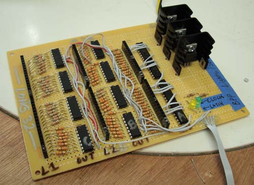
The I/O board before it was completely covered with wires and other crap.
The lamp control and input sensors are connected using 40 pin computer hard drive cables. If I ever do a new machine I’ll probably just have a single PCB made and use card-edge JAMMA connectors. Again, next time.
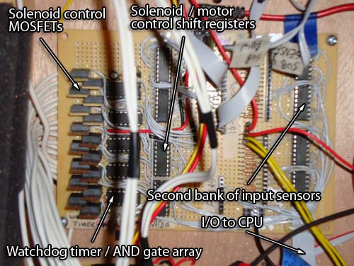
This is the solenoid control board. Again it uses a bank of shift registers to accept serial data from the CPU. This then goes through a series of AND gates which are also connected to a watchdog timer. If the timer doesn’t see clock pulses from the CPU for 1 second it shuts off (sends 0’s) to the AND gates, which keeps the solenoids from getting “stuck on” should the CPU lock up.
Once the +5 volt signals pass the AND gates they goto the Metal Oxide Semiconductor Field Effect Transistors, or MOSFETS. These trigger on a +5 signal (logic level driven) and allow the +24 volt supply to drain through the solenoids on the board (big white wires). Solenoids controlled are as follows:
- Flipper control. Either ON or OFF. The flippers themselves are controller by the player buttons (not CPU triggered)
- Left and right sling targets.
- Ball kicker (kicks ball out of the drain)
- Ball loader (loads new ball into the shooter lane)
- Wife 1-3 ball lock / kicker
- Pop Bumpers 1-3
- Drop Target reset
- Can crusher
- Fish head
The solenoid board also contains a second bank of input sensors. Since the playfield sensors (just barely) fit on the 32 bits of the first bank, this bank is mostly for in-cabinet stuff like the coin door, start button and submarine toy sensors.
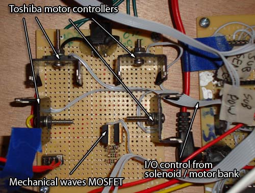
Motor controller board. Pretty simple, it uses spare control bits from the top half of the solenoid bank to control (4) Toshiba Full Bridge DC motor drivers. Motors used are: submarine driver screw, sub launch gate and torpedo trap door open and close. (So the 4th driver just sits there basically). The motors themselves are actually just leftover game controller rumble motors, for some odd reason I have tons of them.
There is also a single MOSFET that controls the mechanical wave motor. This uses +12 volts and “taps” the waves every few cycles to ensure they don’t get stuck. That motor only goes one direction and therefore the gearing mechanism (which I designed and laser-cut myself) has certain spots where it needs a bit more “ompfh” and thus we need a bit of kick should it have to start in that position.
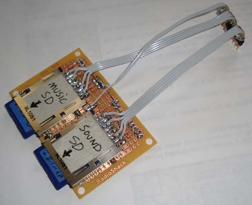
This is the PCB that contains the SD card reader slots. These are accessed directly by the Propeller using routines found here. As is probably evident, one contains the audio clips (voice, sound FX etc) and the other does music. The Propeller actually runs (2) separate FAT file systems and SD reader routines at the same time allowing these cards to be used in parallel.
All sound files are 44,100 16-bit PCM WAV files. The music is primarily from either movies featuring Bill Paxton or his band “Martini Ranch”. Most audio files were made into long loops using Adobe Premiere since that provides a cleaner “loop point” than allowing the Propeller to do it.
The main limitation is the 256 file limit of the FAT driver. This wasn’t really a problem with music but the sound card is almost full with 221 samples, 178 of which are voice clips from movies and the rest are general sound effects for game play. I’ve been collecting sound files from Bill Paxton movies since 2006. I’ll pop in a movie while I work on stuff, and grab sound clips if anything cool comes up.
Despite all of the “Game over, man!” persona, Paxton is actually a fairly soft-spoken actor, so a lot of his dialog in movies isn’t really usable in this fashion. Or to make it usable it needs the volume cranked up quite a bit, such as the case with “Greasy Pork Sandwich served in a dirty ashtray”. There is dialog from co-stars as well, when relevant.
The SD cards themselves hold 2 gigs each, which is ironic considering the actual game program itself must fit within 32k! (That too was pushed to the very limit)
Programming
Making Bill Paxton Pinball consisted of 3 main parts: design, construction and programming. While a full explanation of the programming is beyond the scope of this article, I’ll talk about it a little bit and provide the source code for dissection.
Let me start off by admitting that a) I only know BASIC and b) This is the most programming I’ve done since probably age 15. Back then I loved to program my Atari 800 (which I still have on my desk BTW) but I never really managed to ever finish my games. “New Ben” finishes everything, so that’s no longer a problem.
I had used a BASIC Stamp for several years but knew I’d need to upgrade to the newer Propeller in order to run an entire machine. There are a lot of advantages to the Propeller, it has 8 cores that can truly do multitasking, it has 28 general-purpose I/O lines (plus I2C lines that are freed up after the EEPROM load) and it’s cheap – 8 bucks for the chip itself.

A Propeller on a little dev board I threw together. These things are awesome! This one’s wired to do NTSC video.
The Prop (which I’ll call it henceforth to save wear & tear on my 10 year old keyboard) is controlled by a high-level language designed specifically for it called SPIN. You write SPIN code using a “Propeller Tool” program provided by Parallax that you can find here. Imagine if BASIC and PASCAL hooked up at bar time and 9 months later a new language popped out – well that’s SPIN for you. It’s got a lot of weird quirks but since I’m not really much of a programmer I didn’t mind / notice most of them.
You start by setting up variables:
VAR
long Light0
long Light1
long Blink0
long Blink1
long Chase0
long Chase1
These for instance set up the light data sent to the shift registers, as well as the modifier variables that make certain lights blink or do a 1-2-3 chase. BPP uses around 100 variable in all to keep track of the modes, scoring and debounce.
Debounce is important. Say you hit the Fish Head head. Now the event will trigger the first time the switch closes, but the switch may “bounce” physically or stay closed during more than one kernel cycles. So what we do is set a debounce counter for that target. It starts with the event itself:
if View(Sense, 21) and FishBounce == 0 ‘Fish heads ricochet target
FishBounce := 100
FishHeads += 1
if FishHeads <> 3 ‘At # 3 the fish head sings instead!
type := 4
View(Sense,21) looks at bit 21 of the Sense input. If this is 1 (switch hit, I inverted the input because I like 1’s for switch hits instead of 0’s) AND FishBounce is 0, then it lets us do the Fish Head target thing. This includes setting the FishBounce to 100.
Then, in the main loop (kernel) itself we see this:
if FishBounce
FishBounce -= 1
If FishBounce is not zero, then decrement it by 1 until it is. This sets a timer of sorts which keeps the Fish Target from re-triggering itself until some time has passed, in this case, just under half a second. (The kernel runs at appx 250 Hz) This same type of logic is used for the pop bumpers, sling targets and just about everything else the ball can hit. We can’t really have a “universal debounce” because in multi-ball balls are hitting all sorts of different stuff all at once.
Another important thing the program does is control the sound & music. This is done by using some routines available on the Propeller Object Exchange and then modifying for use in this program. Typical commands are:
Soundloop(99,2,10,255)
This selects audio clip (the 99), bank / movie 2 (Club Dread), and sound clip 10 from that movie (“What are the charges, officer?”) The 255 indicates sound priority. Since only 1 audio clip can play at once we need a way to prioritize them. Each call to SoundLoop checks its new priority value against that of the sound already playing (if any) If the priority is less, the new sound doesn’t play. If it is the same or greater, the new sound plays. Typically high priority is assigned to audio clips relevant to the mode or “launch quotes”, and lower priority is used for general purpose impacts such as the pop bumpers. Thus, if Paxton spews wisdom upon ball launch, the pop bumper impacts won’t interrupt it until it finishes.
Priority levels are also decided by likely shot combos. For example, a shot to the drop targets will often ricochet onto the Hamm’s targets, so Hamm’s is set to higher priority than the drop target sound. Thus we hear the drop target sound, but if it’s not finished by time the Hamms is hit, Hamm’s will then override it. Music files work in a similar way but have no priority, they simply start up new ones when called. Music doesn’t really change all that much, compared to other things.
The display also has a priority setting to it. It also contains routines to allow certain messages to finish scrolling / animating before something new occurs. This mostly occurs on ball drains but also ball locks and some other functions.
The biggest challenge in programming was to keep all of the modes separate and working well together. It’s not as easy as it sounds! For instance, late in the process I decided that the drop targets should do different things depending on mode. That’s fine and all, but what if you start one mode that uses them, but then enter another? (Such as going into the Titanic while Weird Science mode is active) Additional code is required to ensure the currently active use for the drop targets is complete before it is used for the new mode. Also “missions” can be active even though a new mode has started. Then there’s multi-ball to think about!
To study how it was done in detail, you can download the entire Bill Paxton Pinball source code by clicking below. (Reference purposes only, please. No support is implied, so please do not email asking how to use this on your own custom machine)
Bill Paxton Pinball – Source Code
If you’re interested in using the Propeller, Parallax has downloads for all the instruction manuals and reference you could ever need!
In the final section we’ll cover building the toys for the playfield, ramps and final assembly. Stay tuned…
One thought on “Bill Paxton Pinball “Making Of” part 3”