
CNC routing consists of cutting materials with a physical bit or other cutting tool. There are several factors to consider when designing your parts:
Thickness of material / length of bit: We typically use the shortest bits possible to avoid breakage. Here is a breakdown:
- Sixteenth inch bits are best for drilling small, shallow screw holes for sizes 1-4. They are not very effective at cleanouts and are easy to break.
- Eight inch diameter bits are good for cutting thinner materials with more detail and drilling size 6 screw holes. The effective cutting depth is usually 1/2″.
- Quarter inch diameter bits are good for cutting thicker materials, like wood, and removing more material per pass. The effective cutting depth is usually 1″. However, for inner shapes and holes it will have less detail than smaller bits.
- Half inch diameter clean out bits have low detail but can remove a lot of material per pass. They are great for cleaning out large areas.
Good types of material for CNC:
- Wood (solid woods, plywood and MDF) The machine has no problems with these, and MDF (though cheap & IKEA-like) cuts especially well. One issue with wood can be warping, larger sheets of plywood are rarely completely flat, so if your design involves cleanouts (more on these later) add extra depth to compensate.
- PVC Plastics such as Sintra / Komatex lay flat, machine great, provide good strength and can be hand-tooled easily after the fact. I use PVC plastics in most of my prototypes.
- High density foam / wax The ShopBot CNC can mill 3D objects and soft materials are a great choice for this. Easily create a faux sandblasted-looking sign, or mill out a 3D model you’ve design.
Challenging types of material for CNC:
- Thin acrylics & polycarbonates We do not have a vacuum hold down table so while these are possible, we generally avoid them. However, our Epilog Laser can do a fantastic job with them.
- Metals We typically don’t cut these, though the machine can be used with aluminum. Thin sheets of metal would have the same issues mentioned above with acrylics.
- PVC Plastics such as Sintra / Komatex lay flat, machine great, provide good strength and can be hand-tooled easily after the fact. I use PVC plastics in most of my prototypes.
Types of Cutting
There are 5 major types of cutting: male, female, on center, cleanouts and drilling. Below we’ll explain the differences and what to think about with each type.
Male Cutting
This is when a object is selected and the bit cuts around it. The result is a piece of material the shape of the object. An outer male cut is typically the final step that allows a piece to be removed from the material.
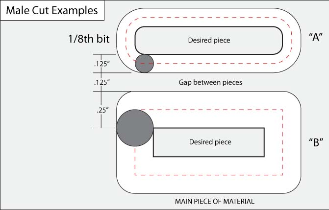
When arranging multiple parts on a sheet, be sure to allow room between the pieces for the gap left by the bit. Failure to do so can result in material instability, excessive vibration and cutting errors.
You can cut any shape you want, but it’s important to remember that the bit is round, so some limitations will occur:
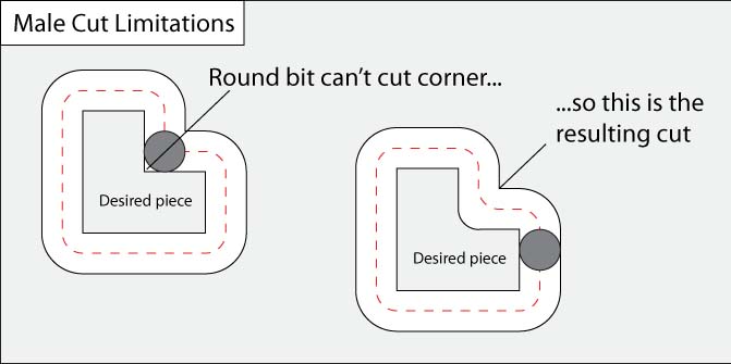
In this example we see that the bit cannot work its way into a tight inside corner, and thus the resulting cut is not the same as the vector shape. For decorative objects this isn’t really a concern, but if you’re designing something that is to be assembled, especially using tongue-in-groove, you’ll need compensate for the round corners. More on this shortly.
Female Cutting
This is when a object is selected and the bit cuts around the inside of it. The result is a hole in the material that can be used for buttons, knobs, displays or tongue and groove slots.
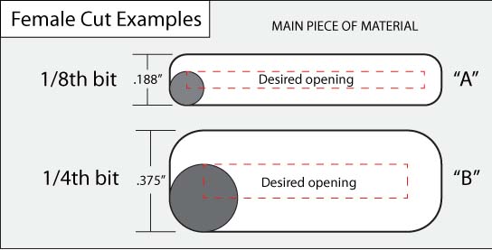
As with the male cut, inside corners will always be rounded. It’s best to plan for this ahead of time by making rounded rectangles where the corner is 1/2″ the diameter of the bit you plan to use. For example, if you’re going to use a 1/8th bit to cut out a hole for a screen, make a rounded rectangle with .063″ corners. This way, the machine will cut exactly what you design, because you’ve planned for the limitations. Remember, just because you can draw it on a computer screen doesn’t mean you can make it in real life.
Female cut shapes always need to be at least slightly larger than the bit diameter to generate a toolpath. So if you’d like to make a slot the same width of the bit (example “A” above) either make a rounded rectangle ever so slightly larger than the bit (even a hundredth of an inch is enough) or make a line segment and do a on center down along it. We typically just make the slots slightly larger so we can group it with all the other female cuts.
On Center Cutting
This is when the bit travels along the center of a vector shape. Unlike male and female cuts, using a line segment (not a polyline) is OK because the bit just needs to follow the center of a line, not find the “sides”.
The best use of on center cutting is making grooves and beveling for existing shapes.
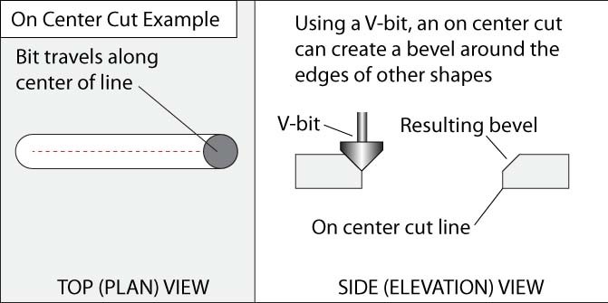
In this example there is a hole for a display. First we cut the vector on center with a V-bit to make a beveled edge. Then we took a regular bit and did a female cut to make the hole itself. The result is a hole with a beveled edge.
Cleanouts
A female cut is typically used to completely remove a shape from the inside of material, basically a hole. A cleanout is like a female cut in that the bit cuts inside the shape, but it mills the entire area and only to a specific depth, like a canoe.
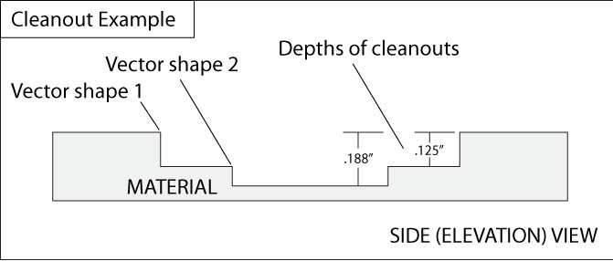
Cleanouts are useful to make hollow enclosures out of solid material, or to create grooves that don’t go all the way through the material and look nicer. Since the bit must clean out the entire inside of a shape, line by line, it takes much long than simple vector cutting and therefore will be more expensive.
Drilling
Drilling is pretty self-explanatory, it’s when the machine drills straight down into the material. Like any other shape, you can drill to any depth you want, all the way or a specific amount of countersink. Very useful for making screw holes.
Be sure that you make your drill circles exactly the same diameter as the bit you plan to use. Eight inch bit requires a .125″ hole, quarter is .25″ and so forth. If you’re using the holes for screws and plan for them to grip be sure your hole is slightly smaller than the screw you plan to use.
Example: A size 6 screw will thread nicely into a 1/8th hole, but to make a hole for a size 4 screw, the 1/8th bit is too large. At that point you’d need to make a .1″ hole and female cut it (not drill it) with the next smallest drill bit, which would be a 1/16th. For screws smaller than size 6, I recommend just drawing a 1/16th hole in the center, using the CNC to drill a pilot hole using that shape, and then drill it manually later.
Solving Tongue & Groove Limitations
A great use of CNC is making wooden or plastic enclosures, and a great way to make those items sturdy is with tongue & grooves. This is when one piece fits inside another. Combined with wood glue and screws, it will make your object even stronger.
However the nature of male and female cuts can cause issues with this, which we will describe and solve below:
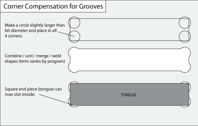
Above we see a groove – what the tongue will slip into it. Assuming the tongue is a flat piece of wood, rounded corners on the groove will be a problem since a 90 degree corner won’t slide into them. Whacking away with a hammer or file could work, but it’s best to just round the outside of the corners as shown above so your piece is routed correctly and it will fit together like butter. We call these “dog bones”.
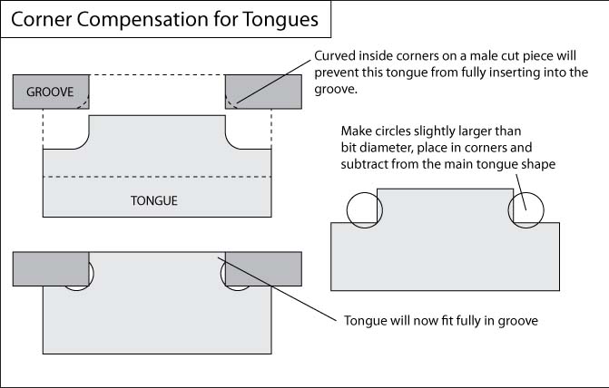
The tongue too may have problems as a result of no tight corners on a male cut. This can be solved by subtracting circles from the inside corners as shown. As long as the circle slightly exceeds the bit diameter, the bit will be able to get in there and clear out enough room for the tongue and groove to fit together at a tight angle.
Software & File Export
We use Adobe Illustrator – a 2D drawing program – for almost everything we cut. Supported file formats that we can import include AI, PDF, DWG, DXF, CorelDraw, EPS, SVG and WMF.
Some art pointers:
- Be sure to draw your items at actual size – do not use a scale feature.
- Arrange your parts on squares the size of the material you intend to use. Leave 1″ space around the sides for hold down screws and clamps. (example, a 48″ x 48″ piece is effectively 46″ x 46″)
- There is no need to solid color objects, just a stroke outline is fine.
- All text should be rasterized (made non-editable) for maximum export compatibility.
- Depending on program, you may subtract / add a shape but it is just in preview mode before you expand / finalize it. The same applies for text effects. View your art in wireframe to see what the vectors actually are.
- Do most of your work in wireframe view for best results.
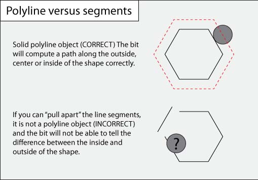
One important thing to note is that exported vector files must be polylines (contiguous lines, not line segments) so be sure your export format supports that, or you check the box to enable it. You should also avoid special characters such as Illustrator symbols. Read this for more information – you’ll want to export objects like the closed polygonal chain.
There are examples of when you’ll want a single line segment, for instance if you’d like the machine to on center cut a V-groove along just one side of an object.
For 3D milled objects, the software supports STL, DXF, OBJ and others.
If you’ve got an idea for a project but need drawing software consider Inkscape. It’s free and open source, and its default SVG file format opens perfectly in Illustrator.
Once you’ve gone over all of this, please email us to discuss your idea. Thanks and we look forwarding to working with you!