
Here’s something done several months ago but just now showing up on the site – a response time test controller built for use by Infinity Ward for a new game they are working on.
Includes world’s most colorful ribbon cable!
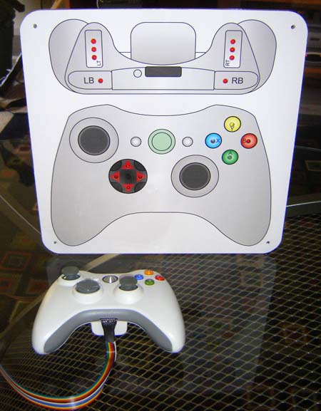
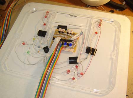
The idea behind this project was to build a system which shows the pressing of the buttons in a very obvious manner, in this case LED’s. The controller wiring is piggy-backed, and an extension port added to the bottom of it. This then connects to the main lightboard, indicating exactly when buttons are pushed.
The intent is that this is filmed for testing purposes to help identify the gap between when users are pressing buttons and when onscreen actions actually occur.
If you think something like this might be of use to your company, or have a similar idea, why not drop me a line?
For making-of info, sample videos and pics of the unit being tested, check out the rest of the story below. To read the original article that inspired the customer to have me create this, click here.
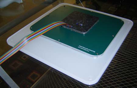
Back of the display board. There’s not a whole lot to it, so it’s quite thin.
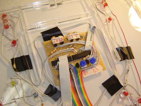
Close-up of the driver circuit. Newer Xbox 360 controllers use a simple active-low button scheme, and in this mod these signals are all sent to a pair of octal buffer/drivers (the 2 IC’s seen in the pic). The drivers send a “copy” of the input data to their output lines, ie, if pin 2 is LOW, corresponding output pin 18 is LOW and can trigger an LED.
This allows an isolation from the Xbox 360 controller functions themselves, probably a bit over-engineered but the IC’s are cheap enough so who cares? The lightboard itself is powered by the controller’s 3.3 volt accessory line (where the chat pad hooks up) so it powers on when the controller does.
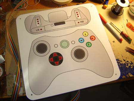
The lightboard itself is just a piece of laser-cut acrylic with a graphic slapped over it. It is 200% the size of a normal controller, allowing for easy videotaping. The LED’s on the 4 main buttons are the same color as the buttons themselves, just to make things a little more obvious. (The rest of the LED’s are red because that’s the cheapest color 🙂
Kind of like an old air traffic control board, in a way.
Action Videos!
Testing digital button outputs. This was quite simple… again had I used an older Xbox 360 controller it would be a different story.
Testing analog shoulder button bar graph. This was a little trickier… I ended up making a resistor ladder to convert the analog signal to a digital (progressive) LED layout. Using potentiometers (as the resistors) allowed me to dial in on the correct settings, and also adjust it so it wouldn’t interfere with the data going back to the Xbox.
Testing controller with Grand Theft Auto 4, which was the hotness at the time of construction. That plant in the background has since died, unfortunately. Apparently the TV didn’t provide it enough light or something…
Awesome piece of work.
Infinity Ward’s controls for COD4 are so responsive and tight. I assumed they were sharply aware of the interaction between the user’s hands/mind and their code, but your commissioned controller is the evidence of what makes them so great.
On the other hand, I was talking to a friend about how shitty the Force Unleashed-Star Destroy battle was. My friend said he passed that level with ease once he released that the quicktime event’s onscreen instructions were basically wrong. Not only would your 360 controller would be perfect to demonstrate the “right” way to solve that level, but if your controller was available to those guys at that time maybe they wouldn’t have released such a broken level.
I remember seeing a drawing of this around greeleys back in the summer months, finally know what it is!
Wow man, that is great! I did’nt know that you made stuff for the industry like that!
could this be for use for the new cod6????!!?
i HOPE SO!
I was impressed by Infinity Ward going the extra mile and ordering one of these.
I actually used to visit a computer shop 20 or so years ago and the guy in there had made on of these to test if joysticks worked. His was much more primitive and was not used for resonse times, it was there to see if a fault lay with the computer or the controller. at the time I thought the guy must be a genius. So thanks for bringing back some terrific memories of saturday afternoons spent in that shop.
Any pictures of where you made the connections inside the controller? I’m doing a controller hack that needs to hijack the button outputs in a similar way. I’m using the active low button style controller too but there doesn’t seem to be any good locations to hijack the buttons short of soldering directly to the main IC or scratching the protective coating off of a trace…
Twisted, I’m not sure if I have any. I think I scraped the lines and intercepted the signals just outside of the rubber domes (so they wouldn’t be affected)
It isn’t the easiest soldering in the world, to be sure. But doable.
-Ben
Well I chose to use a space time contiuom device that denotes each magnetic pull in which a button uses. I promulgated the equalateral triangle flangee and added some volt meter devices to decipher its input. I found that by sticking my finger up my ass I became aroused.
the latest version of Grand Theft Auto have more detail on its graphics, nicely done.`:;
i used to play Grand Theft Auto a lot but i kind of got busy these days so i dont play it anymore-*:
i operate a small computer shop at home and most customers enjoy playing online games ::’